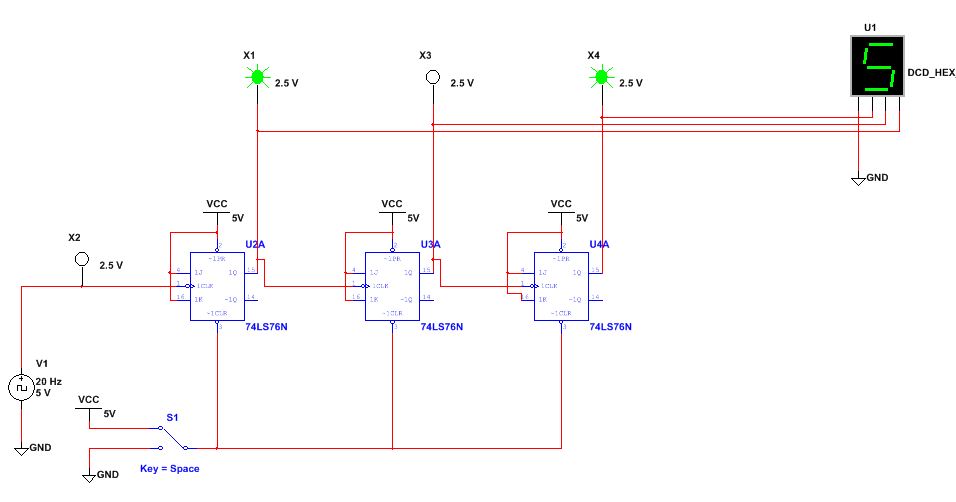
3 bit asynchronous counter using jk flip flop
In the previous section, we saw a circuit using one J-K flip-flop that counted backward in a two-bit binary sequence, from 11 to 10 to 01 to Since it would be desirable to have a circuit that could count forward and not just backward, it would be worthwhile to examine a forward count sequence again and look for more patterns that might indicate how to build such a circuit.
The main problem facing us is to determine how to connect these flip-flops together so that they toggle at the right times to produce the proper binary sequence. Note that each bit in this four-bit sequence toggles when the bit before it the bit having a lesser significance, or place-weight , toggles in a particular direction: The Q outputs of each flip-flop will serve as the respective binary bits of the final, four-bit count:.
The first flip-flop the one with the Q 0 output , has a positive-edge triggered clock input, so it toggles with each rising edge of the clock signal.
Asynchronous Counters | Sequential Circuits | Electronics Textbook
In the very first flip-flop circuit shown in this chapter, I used the clock signal itself as one of the output bits. Unfortunately, all of the counter circuits shown thusfar share a common problem: This effect is seen in certain types of binary adder and data conversion circuits, and is due to accumulative propagation delays between cascaded gates. When the Q output of a flip-flop transitions from 1 to 0, it commands the next flip-flop to toggle.
If the next flip-flop toggle is a transition from 1 to 0, it will command the flip-flop after it to toggle as well, and so on. Thus, when multiple bits toggle in a binary count sequence, they will not all toggle at exactly the same time:.
As you can see, the more bits that toggle with a given clock pulse, the more severe the accumulated delay time from LSB to MSB. This behavior earns the counter circuit the name of ripple counter , or asynchronous counter.
In many applications, this effect is tolerable, since the ripple happens very, very quickly the width of the delays has been exaggerated here as an aid to understanding the effects. There is a way to use this type of counter circuit in applications sensitive to false, ripple-generated outputs, and it involves a principle known as strobing.
In most cases, the strobing signal can be the same clock pulse that drives the counter circuit:.

If not, the clock signal will prematurely enable the receiving circuit, while some rippling is still taking place. Another disadvantage of the asynchronous, or ripple, counter circuit is limited speed. While all gate circuits are limited in terms of maximum signal frequency, the design of asynchronous counter circuits compounds this problem by making propagation delays additive. Thus, even if strobing is used in the receiving circuit, an asynchronous counter circuit cannot be clocked at any frequency higher than that which allows the greatest possible accumulated propagation delay to elapse well before the next pulse.
The solution to this problem is a counter circuit that avoids ripple altogether. This design of counter circuit is the subject of the next section. Published under the terms and conditions of the Design Science License.
Digital System Tutorial: 3-bit Synchronous down counter with JK flip-flops
ARTICLES LATEST NEWS PROJECTS TECHNICAL ARTICLES INDUSTRY ARTICLES. Textbooks Video Lectures Worksheets Industry Webinars By Category. Calculators Part Search Test Equipment DB BOM Tool Code Library. IV - Digital Sequential Circuits Asynchronous Counters. The Q outputs of each flip-flop will serve as the respective binary bits of the final, four-bit count: Thus, when multiple bits toggle in a binary count sequence, they will not all toggle at exactly the same time: In most cases, the strobing signal can be the same clock pulse that drives the counter circuit: Another way is to use negative-edge triggered flip-flops, connecting the clock inputs to the Q outputs of the preceding flip-flops.
These types of counter circuits are called asynchronous counters , or ripple counters.
Asynchronous Counter
Strobing is a technique applied to circuits receiving the output of an asynchronous ripple counter, so that the false counts generated during the ripple time will have no ill effect. You May Also Like: An Introduction to Audio Electronics: Sound, Microphones, Speakers, and Amplifiers Learn about the basics of audio electronics, which convert sound signals into electrical signals, process these electrical signals, and Implementing I2C with an EFM8 Microcontroller, Part 2 Firmware architecture and example code for an I2C interface based on the Silicon Labs SMBus peripheral.
The Bartlett Versus the Rectangular Window In this article, we will discuss the fact that choice of different window functions involves a trade-off between the main lobe width and the WHO WE ARE More about us. Content News Projects Technical Articles Textbook Industry Articles Industry Webinars Test Equipment BOM Tool.
Giveaways Video Lectures Worksheets Forum Calculators Electronic Components Code Library. Categories Latest Automotive Analog Arduino Projects Connectors Digital ICs Electromechanical Embedded. Connect with Us Facebook Twitter YouTube LinkedIn. Contact Us Write For Us Advertise Newsletters.